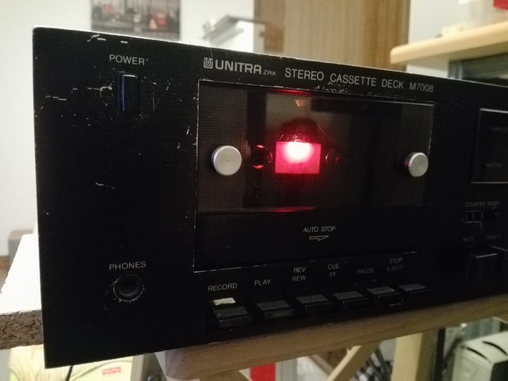
That was some evening. I was sitting in my office sourounded by papers, when suddenly phone rang. It was Tom von Tre. He made me a proposal that I couldn't not refuse. A moment later he came with his dying tape recorder Unitra Deck M7008 ask for taking care of it. I already knew, it won't be easy case, because we haven't had such patient yet, but we must accept new chellenges.
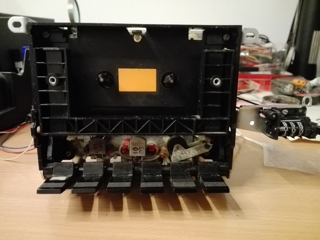
First look showed that there is a much will to live in it. Owner told about problem with reading header. Unfortunately there were more problems. Only half of bulbs were still working. Mechanism required cleaning. Only some rubber stripes were replaced with new. Counter drive was missing. And it turned out to be only a top of iceberg.
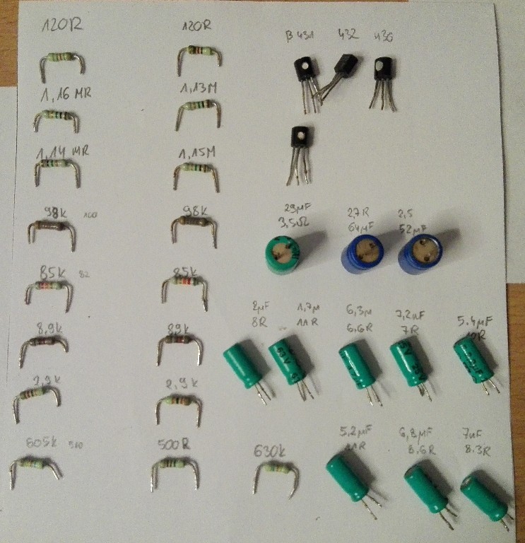
For this kind of work, it is good to have a schematic. It is impossible to find one to M7008 but it is much easier for M7010, which differs only in details. Precisely speaking M7008 is M7010 without some modules. With schematic in hands we can start to check electrolitic capacitors. Check all of them took me some time, but it was worth. Some of them was ready to go ;).


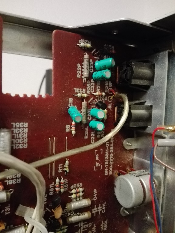
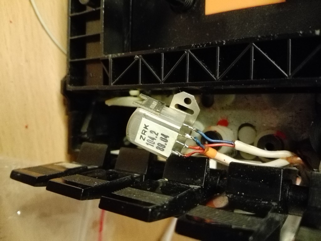
In this device for noise cancelation were mounted two types of modules DolbySurround or CSNR-2. On my schematic there was no module that I found inside, to I dug a bit more in the Internet to know what I measure and what kind of parts should be there.


When this is ready, it is time to check voltages in some key points. And another drama. Voltages were not equal neither between channels nor with those given on schematic. As investigation showed, blame was on resistors and its high tolerance. Some of them different values in each channels. Fortunatelly I managed to find right ones.
When voltages were done, it was time for tape header. I was hoping that cleaning will do the job, but as you can see on photo, old one was almost scooped. From the Internet, I found out that for this model ALPS part fits but require change in pre-amp and I was still missing some data to make this correction. I searched for original part and I got brand new one.
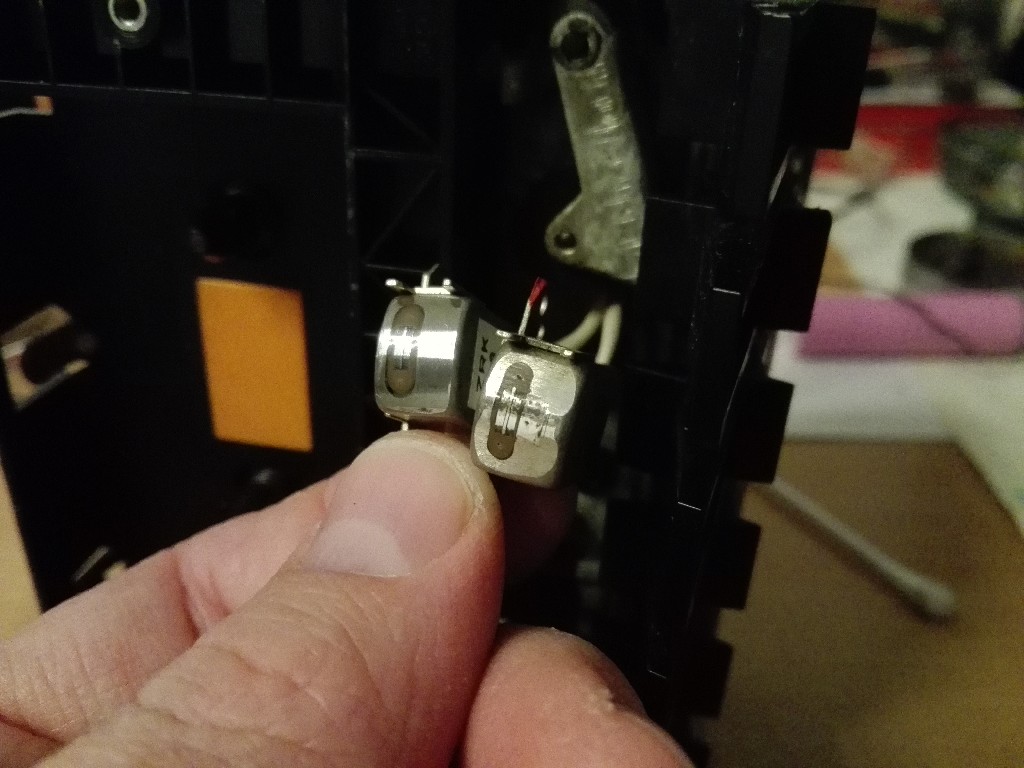
Even though, I used exactly the same model of tape header, I had to tune all parameters from scratch. For this purposes, we need some special tape recorded with set of waveforms of given frequences. This kind of tape is available in the Internet, but original one are quite old and I don't trust them. I managed to find what should be on such tape and using modern technique prepared one. Armed with multimeter, osciloscoupe, screw driver and service manual I could fight a battle like it was done in factory. This task is not easy, but very necessary.
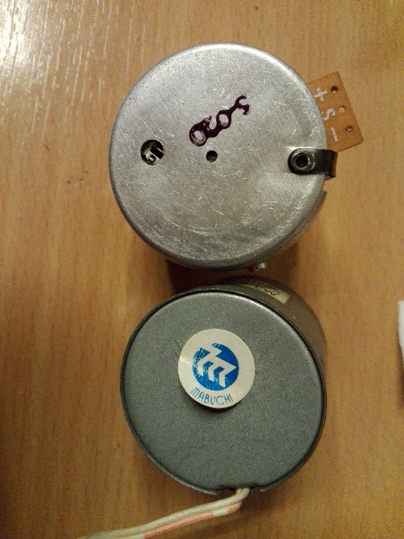
Last thing to do after setting up currents and sensitivity is to tune tape speed. As you can easily figure out, DC motor is responsible for that. I found interesting fact - this mechanism is copied to a single screw from western tape recorders. Even counter placement and bulb behind tape. DC motor was made in Poland. Its name was SILMA. Unfortunately our engineers didn't make the best job and this part was one of the most failing parts. When I ran this deck, i noticed that tape runs slower and faster. On the beginning I blamed mechanism with gears, but after complete disassembly and cleaning situation wasn't much better. Internet told me that in the past this part had been replacing with japan equivalent from Mabuchi. They are available in China, but expected time of arrival is aproximetly 3 months. I found a few in Poland. When first one came, it turned out to be on different voltage and oposite spining direction. Learnt my lesson and ordered another one. I knew direction was also wrong, but changing polarisation is not a problem. At least I thought that. Unfortunatly, in oposite direction, motor was not strong enought to rewind tape. I was going to hang white flag and give up, but I reminded myself about my own collection of motors. Believe or on, but in all gathered (about 30 pieces) I had only one Mabuchi on 12V. It would be to good to be true, so my motor didn't have any rpm regulator. I put it for test to the deck. It was running like a wild horse on drugs but with constant velocity. So I only had to make regulator and job would be done. First thought was about resistor in series, but there was a risk, that I will loose its power. In the end I decided to use PWM. Prototype turned out to be better that I could even expected, so I made custom board and soldered it on the back of DC motor.


As a last step, I replaced all burned bulbs and add missing rubber stripes. I was happy to anounce family that surgery had been successful.